MULTI-SECTION MANIFOLDS AND INSULATED MANIFOLD ENCLOSURES TERRA BOX SERIES
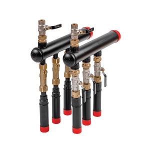
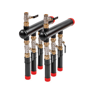
Multi-section manifolds with rotameters Series R and with valves Series Z form a component of the PRAWTECH geothermal system: ground heat sources for heat pumps. The manifold has been designed to ensure access for basic regulatory and service operations. The manifold is dedicated to wall-mounted installation inside or outside a building; alternatively, the manufacturer permits installation of the product in a plastic or concrete protective chamber designed for this purpose in the ground.
Manifold construction:
The Prawtech ground heat source hydraulic manifold consists of two collector beams made of HDPE100 material with outlets (referred to as ground heat source sections).
– Supply collector beam is equipped on each section with brass linear flow meters with a range of 8–38 l/min. The rotameters enable flow reading and regulation, as well as shut-off of a given geothermal installation section via a ball valve integrated into the flow meter body.
– Return collector beam is equipped on each section with a shut-off ball valve. The beam enables complete individual shut-off of each ground heat source circuit.
Flow regulation must be performed exclusively through rotameter adjustment. Valves are used for flow shut-off only.
Each collector beam of the multi-section manifold is equipped with a ¾” GW type venting/filling valve assembly for systems with 2 to 6 circuits, and 1″ for larger manifolds. This section allows for effective flushing, filling and venting of the ground heat source system.
The manifold is responsible for transporting antifreeze fluid from the heat pump to the ground/rock formation and back to the heat pump plant room. The products are designed for use with any antifreeze fluid.
Fluids recommended by the manufacturer are propylene and ethylene glycols with corrosion inhibitor and anti-foaming additive packages. More details available in: PRAWTECH Chemical Resistance Data Sheet.
The design of the geothermal manifold also enables correct flushing, filling and venting of the ground heat source installation.
Before installing the manifold, ensure that the mounting surface guarantees safe operation, stable fixing of the system and access for service operations. The hydraulic manifold has a universal design. The use of disconnectable screwed fittings allows the product to be adapted to the layout of equipment in the heat pump plant room by setting the flow meters and shut-off ball valves in either right or left position. The manifold does not include a mounting bracket as standard. It is recommended to use standard market-available mounting techniques: mounting profiles, bolts and clamps.
NOTE
Thermal insulation of the ground heat source manifold is always recommended when the product installation location is inside a building, within heated rooms. More details in the PRAWTECH Ground Heat Source Installation Requirements.
Section and inlet pipe configuration of multi-section manifolds
All PRAWTECH multi-section manifolds are equipped as standard with 40mm ground heat source sections. The inlet pipe diameter is 63 mm for manifolds with 2–6 sections, and 90 mm for larger configurations.
The supply and return sections of the manifold must be installed in two parallel levels. The axial distance between sections is 10 cm.
NOTE
Individual manifold configurations are available at special prices. The surcharge is defined by the manufacturer on a case-by-case basis and depends on the scale and scope of individual applications. All PRAWTECH multi-section manifolds are delivered to the customer only after successfully passing pressure and flow tests in accordance with the in-house quality control procedure. As an alternative to Series R manifolds equipped with linear flow meters, the manufacturer offers Series Z manifold configurations with valves. The Z range has an identical design except that a ¾” ball valve is used on all sections of the supply and return beams instead of a flow meter. Series Z manifolds do not perform the flow reading and regulation function. Series Z products are available in the manufacturer’s catalogue under separate commercial codes.
MULTI-SECTION MANIFOLDS AND INSULATED MANIFOLD ENCLOSURES TERRA BOX SERIES
Insulated Terra BOX manifold enclosures with rotameters Series R and with valves Series Z form a component of the PRAWTECH geothermal system: ground heat sources for heat pumps. The enclosure design ensures access for basic regulatory and service operations. The product is dedicated to wall-mounted installation inside or outside a building, both in flush-mount and surface-mount configurations. In the case of so-called warm installation of the enclosure within external building insulation (e.g. polystyrene or mineral wool), an optional element – the fascia/mounting frame available in the PRAWTECH GEOTHERMAL range – should be used. This ensures the proper installation aesthetics of the offered solution.
Terra BOX enclosure manifold construction:
The Prawtech ground heat source hydraulic manifold installed in the insulated Terra BOX housing consists of two collector beams made of HDPE100/RC material with outlets (referred to as ground heat source sections).
– Supply collector beam* is equipped on each section with brass linear flow meters with a range of 8–38 l/min. The rotameters enable flow reading and regulation, as well as shut-off of a given geothermal installation section via a ball valve integrated into the flow meter body.
– Return collector beam is equipped on each section with a shut-off ball valve. The beam enables complete individual shut-off of each ground heat source circuit.
*applies to Series R. When purchasing a Series Z enclosure, flow meters are replaced by shut-off ball valves.
Flow regulation must be performed exclusively through rotameter adjustment. Valves are used for flow shut-off only.
Each collector beam of the multi-section manifold is equipped with a ¾” GW type venting/filling valve assembly. This section allows for effective flushing, filling and venting of the ground heat source system.
The manifold is responsible for transporting antifreeze fluid from the heat pump to the ground/rock formation and back to the heat pump plant room. PRAWTECH GEOTHERMAL series products are designed for use with any antifreeze fluid. Fluids recommended by the manufacturer are propylene and ethylene glycols with corrosion inhibitor and anti-foaming additive packages (e.g. fluids available in our range such as PRAWTECH EKO KP or PRAWTECH KE). More details available in the section: Downloads.
Terra BOX housing:
The Terra BOX multi-section enclosure housing is made of double-side painted steel with additional anti-corrosion protection. All surfaces of the enclosure have been thermally insulated with rubber foam matting to eliminate condensation on its outer walls. The enclosure is manufactured to a standard providing UV protection.
Standard equipment of the enclosure includes key-locked (patent lock) inspection doors. Enclosure colour: RAL 9003
Section and inlet pipe configuration of the Terra BOX enclosure manifold
All PRAWTECH multi-section manifolds are equipped as standard with 40 mm ground heat source sections. The inlet pipe diameter is 50 or 40 mm. The inlet pipes of the external enclosure exit from the rear wall of the enclosure, perpendicular to the mounting surface. In the version designed for installation inside a building, the enclosure is equipped with inlet sections located at the top of the housing. The axial distance between ground heat source sections is 8 cm. The enclosure is available in 2 and 3 section configurations.
Details of the offered solutions are available in the technical data sheet in the section: Downloads.
PRODUCTS:
|
|
|
|
|
|
|
|
|
|
|
|
* inlet pipes with diameter 40 or 50 mm exit from the rear of the Terra BOX enclosure housing. The enclosure housing is thermally insulated.
Rotameter configuration.
|
|
* inlet pipes with diameter 40 or 50 mm exit from the rear of the Terra BOX enclosure housing. The enclosure housing is thermally insulated.
Valve configuration.
|
|
* inlet pipes with diameter 40 or 50 mm exit from the top of the Terra BOX enclosure housing. The enclosure housing is thermally insulated.
Valve configuration.
|
|
* inlet pipes with diameter 40 or 50 mm exit from the top of the Terra BOX enclosure housing. The enclosure housing is thermally insulated.
Rotameter configuration.
| Terra BOX manifold enclosure frame |
| code OZEBOXRAMKA |
**inlet pipes with diameter 40 or 50 mm exit from the rear of the Terra BOX enclosure housing. The enclosure housing is thermally insulated.
Automated page speed optimizations for fast site performance